Metal drawing has been my everyday staple in my line of work, and I have vast experience working in metal stamping manufacturing companies. Most of what I’ve produced with most companies are machine parts and cylinders for electrical appliances, most being custom designs for client businesses and companies. Metal drawing is the simplest of all metal shaping processes since its procedure is minimalist, less like progressive die stamping or fabrication. But while I’ve dealt with simpler metal drawing designs, for the most part, my operations have also tagged complex contours and model designs. This article will offer insight into deep metal drawing and the nitty-gritty involving deep metal drawing.
What Is Deep Drawing?
Deep drawing is the metal forming process involving the redial drawing of a sheet blank to form a cylinder or dome-shaped component. Usually, a metal punch administers the hydraulic force, which is metered and predetermined depending on the blank sheet material. Numerous factors for successful metal drawing involving the thickness and material used to come into play. Besides, the clearance (the extra thickness to compensate for material stretching) is a critical preliminary in deep drawing. The die corner and punch radii are also essential measurements for workable products.
Crucial Deep Drawing Elements to Consider
As the metal stretches during the drawing, it becomes thinner and less sturdy. And that’s why it’s critical to measure the ramming force and the sheet blank to be used. I’ve worked with numerous die dimensions, and it’ll be not very objective to think these measurements are cross-cutting. The products are usually nuanced by size, shape, and potential uses, making isolated deep drawings varied.
The critical elements include:
Material Type and Thickness
I’ve worked with all metal sorts, but I can attest to the strength and reliability of a few. Stainless steel is my best pick, but aluminum and copper still get my approval. Alloys might be sturdy, but when working as sheet blanks for deep drawing, they usually give in to the pressure from the ramming. Besides, it is critical to work with thick sheets. Usually, the material element gets subjected to strong tensile and compressive forces, and therefore, thinner sheets will tear quickly.
Draw Ratio and Radii
Draw ratios determine the maximum deep drawing amount on a sheet metal blank. In a standard industrial-scale operation, the force requires some proper gauging. In this case, the thickness and type of sheet metal blank determine the draw ratio. The coefficients come from the metal flow, geometry, and material. Also, the radius should be about 6 to 8 times the material for the material to flow with ease.
Die Temperature
In industrial-scale operations, manufacturers instrument their dies with thermocouples to calculate the amount of heat generated. That’s crucial since heat-generating friction is usually likely during deep drawing and impacts the results. Heated sheets and dies marginally expand, which interferes with the predetermined measurements. Besides, the high temperature lowers the lubricants’ viscosity, making them less effective in reducing the stretching and punching forces.
Blank Size and Shape
The size and shape of the blank determine the sheer and tear capacity. Besides, it enables the blank holders to grip it in shape, and the larger it is, the better to provide a wide surface area for the draw beads. The shape also matters since they determine the product type and the results. Circular sheet blanks are sought-after, but square ones are also popular. However, for the latter, material flow towards the four corners is compressional and may slightly distort the material, interfering with the material flow.
Press Speed
Deep drawing operations that involve punching slots on blanks have immense speeds compared to the standard shape-forming ones. However, the type of sheet blank material used determines these speeds since materials like copper don’t have similar capabilities as steel. Unmetered higher press speeds can wreak havoc on the material, especially copper or aluminum. And if perforations are necessary, it’s best to carry out the operations separately.
Drawing Lubricants
Lubricants help reduce the friction resulting from the stretching forces better. When punching the metal sheet, there’s usually some resistance level, leading to tear and wear. And more often, it can distort the shapes or result in poor quality products. The glad tiding is that numerous lubricants are available, including emulsions, drawing oils, and lubricants containing oil and solid substances. Some lubricants are soap-based and applicable through manual wrapping using a rag, flooding, or roll coating.
Other elements for perfectly finished draw products include the binder pressure, draw height and shape, and standoff height. Besides lubricant use, the part geometry and the die surface finish result in the perfect, efficient, and workable metal draw products, all of which need consideration.
How to Deep Draw Metal Sheet: The Process
I prefer using simulation software rather than making measurements off the top of my head or manually calculating them. It’s a pretty sure way of getting the best results with the projected models having the dimension needed. My best software, Autoform, is second to none, and it’s the most intuitive, providing the best simulations with correct measurements. However, there is still some other proficient software, including Castyield Precision and NG Engineering. Here’s my familiar metal deep drawing process.
- Designing the Deep Drawing Operation
Numerous calculations must tick right before carrying on with deep drawing. And while I use simulation software from time to time, doing it the old-school way still works better. When operating the dies, I usually use the blank sheet to help me determine the amount of the punch and blank holder. Since the blank has its specific material, shape, thickness, and radius, the punch amount consequently varies. Besides, calculating the surface area of the finished product helps me determine the radii to work with. Also, adding an extra material percentage helps create a flange for the blank holder, which I cut off later.
- Positioning the Blank on the Stripper
The metal sheet blank needs to be firmly in position, and therefore, engaging the blank holder and die come in handy. The blanking and drawing punch needs a tinier clearance, or none, as the draw bead firmly grasps against the metal sheet. Here, I prefer applying some lubrication, smearing it on both sides of the metal drawing machine. That helps reduce friction and heat generation quite significantly. Movable strippers can still do the work, but technically, fixed
- Pressure Generation
Once the metal sheet is in place, blanking follows. That involves letting the punch ram against the metal sheet to create the desired geometric shape. I usually prefer slow ramming speeds since faster speeds might infuse fissures, wrinkles, and tears. However, if the process requires that I punch a few holes, I prefer quicker speeds. That means I have to use sturdier and thicker metal sheets for the material to contain the pressure.
- The Drawing Process
The stroke usually edges more deeply into the pressure medium, pulling the blank metal sheet. And as the blank stretched down, it permanently deforms in the required shape. After the drawing reaches the bottom dead point, it stops. That only happens after feeding the deep drawing machine with the desired metrics, including the ideal drawing force and the correct measurements. I usually don’t control anything from here, and I let the machine do the punching before knocking it out.
- Withdrawing and Finishing
After the drawing, the draw bead and black holder disengage and move up. The metal should be deformed and ready for pulling before placing the next sheet. And sometimes, the edges can be rugged, requiring some smoothening and finishing. The round blank metal sheet doesn’t need edge trimming since they’re regular and ready. However, products formed from square blanks need some checking to obtain uniformity.
Defects in Deep Drawing
Sometimes, the drawing products don’t turn out perfectly due to defects. That’s pretty normal for me since miscalculations are possible, and you may overestimate the force, under-measure the radii, or work with high temperatures. Typical defects include thinning towards the base of the formed cylinder due to excessive pressure or overstretching of the material. Besides, materials such as copper have the sheer ability to fracture or tear easily. Square blank sheets can sometimes attract ripples and folds towards their corners, leading to defective products.
I usually get my measurements correctly, and the estimations are spot on to prevent tearing. And since it’s generally challenging to get these measurements off the top of my head or make manual calculations, I use simulation software. They’re better to obtain the best measurements once you feed them with your expected end products’ dimensions. They also help calculate the amount of the punching force and flow on the blank so that it doesn’t exert a lot of it to cause tearing, thinning, and wrinkling.
Why Blank Optimization Is the Key
To prevent distortions and defects, I usually optimize my blanks since that’s where things go wrong for most operations. Using more extensive material interferes with the flow. Besides, a blank metal sheet with uneven thickness increases the forces that act on the blanks and can lead to breaks and tears. Excessive temperature can also alter the dimensions, increasing them slightly and interfering with the forces’ accuracy and the products’ cavities.
It’s, therefore, possible to prevent defects resulting from irregular dimensions or excess material. And my best way to avoid that is to project the dimensions of the final product first, which I feed into the simulation software. That gives me the exact measurements of the metal sheet radii, the best suitable material, and the ramming or punching force to work with. Trial and error methods can still do the trick, but that can be near impossible if I make repeated mistakes without knowing what needs fixing.
How to Perform Irregular Deep Drawing
So far, I’ve vastly touched on making standard deep drawing shapes that don’t require complex parts. However, sometimes clients demand non-standard deep drawing shapes, including domed, stepped, and tapered designs. That can be challenging since creating these shapes requires extra double work, sometimes combining two or more drawings or reshaping. That’s true with making tapered designs since they usually have a narrowed base that attracts a resistance to material flow.
In that case, tapered shapes require making stepped models first before finalizing by straightening the bends and indents. Hemisphere domed shapes are minimalist versions closely similar to the standard cylinder shapes. However, a few dimensions to consider, and software like Sketchup can help. This software is intuitive and straightforward, and I’ve had to use it severally to create domes before deep drawing them. That helps determine the exact dimensions and deep drawing punching force to use.
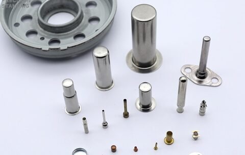
Possible Uses of Deep Drawing Components
Over the years, I’ve manufactured deep drawing components for numerous industries, including homeware and industrial materials. Deep drawing components also have a variety of uses in the automotive and packaging industries. They’re usable in creating automotive moving parts, including engine piston cylinders and appliances such as electric kettle shells and cooking pots. Faucets, sink, and bathtubs are numerous components resulting from deep drawing.
Virtually every manufacturing industry uses deep-drawn components, most being parts including assembly housing and electronic relays. The deep, complex functions are also a staple in making more sophisticated plane engine parts in the aviation industry. However, they’re usually sturdy and manufactured with high precision to allow no room for error. The uses for metal drawing components aren’t limited to a few but stretch across almost every aspect of production.
Conclusion
Metal deep drawing is a significant operation that conveys material components to a vast array of fields, including manufacturing. The manufacturing process is intuitive and pretty straightforward, but there are a plethora of factors to consider to make it successful. The essential requirement is to work with a suitable thickness, material, and blank size. But choosing the best lubricants, correctly calculating the draw ratios and radii, and working with the needed temperature conditions yield the best results. More complex components require utmost precision, and software, including SketchUp and Autoform, can help make the preliminary sketches and designs.